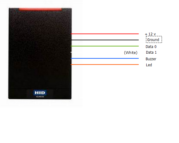
Step 3: Connect the card reader’s data wires. Identify the data wires of the card reader, which are usually labeled “Data0”, “Data1”, “Clock”, and “Ground”. Match the data wires with their corresponding terminals on the access control device or card reader controller. Use wire connectors or soldering to secure the connections.
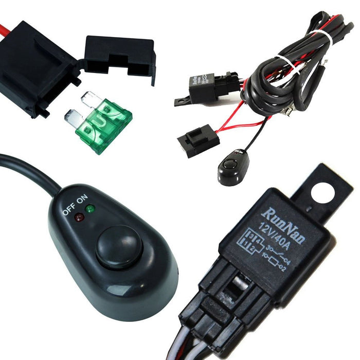
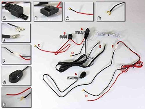
Universal Relay Harness Wire Kit + LED ON/OFF Switch For Fog Lights HI — iJDMTOY.com
Summary of Contents for HID iCLASS RK40. Page 1 instalación installation instalação installation installazione 安装 取り付け 설치 УСТАНОВКА iCLASS ® 13.56 MHz Contactless Smart Card Readers with Keypad INSTALLATION GUIDE RK40 RWK400 RPK40 6404-901 A.3… Page 2 • 1 – 底板 Consigliati • 5-9 жил (Wiegand или RS232

Source Image: s.click.aliexpress.com
Download Image
Document Library. HID® Signo™ Reader Installation Guide. HID® Signo™ Reader Installation Guide. Posted date: 06 May 2020. Download.

Source Image: pinterest.com
Download Image
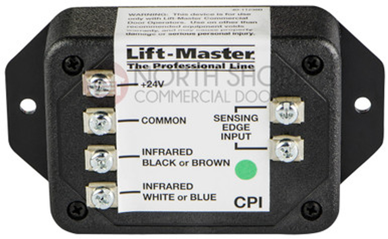
Liftmaster 41K4629 Safety Beam CPI Interface Box-Garage Door Opener CPS Summary of Contents for HID iCLASS SE. Page 1 The facility code needs to be manually entered as 3 digits (i.e. if facility code is 10 enter 0-1-0- tamper will sink to ground from its default 5VDC. Contact HID Technical Support for Optical Tamper #). Note: SE readers only use facility codes between 1-255, and there is no default facility code.
Source Image: securitysystemstory.com
Download Image
Hid Card Reader Wiring Diagram
Summary of Contents for HID iCLASS SE. Page 1 The facility code needs to be manually entered as 3 digits (i.e. if facility code is 10 enter 0-1-0- tamper will sink to ground from its default 5VDC. Contact HID Technical Support for Optical Tamper #). Note: SE readers only use facility codes between 1-255, and there is no default facility code. Review the wiring diagram provided with the HID R10 reader. Pay close attention to the different components and their connections. Step 3: Connect the power supply. Identify the power supply terminals on the HID R10 reader and connect the positive and negative wires accordingly. Make sure to use the appropriate wire connections and secure them
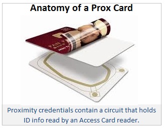
Access cards and readers Access cards and card readers
Connect the Data0 and Data1 lines from the card reader to the appropriate input on the control panel. Connect the control panel to the locking mechanism, following the manufacturer’s instructions. If necessary, connect any additional components, such as an exit button or door sensor, according to the wiring diagram. HID MaxiPro 5375 AGN00 125 kHz Long Range Proximity Reader

Source Image: edlocks.com
Download Image
How to Program HID Proximity Cards Connect the Data0 and Data1 lines from the card reader to the appropriate input on the control panel. Connect the control panel to the locking mechanism, following the manufacturer’s instructions. If necessary, connect any additional components, such as an exit button or door sensor, according to the wiring diagram.
Source Image: idcardgroup.com
Download Image
Universal Relay Harness Wire Kit + LED ON/OFF Switch For Fog Lights HI — iJDMTOY.com Step 3: Connect the card reader’s data wires. Identify the data wires of the card reader, which are usually labeled “Data0”, “Data1”, “Clock”, and “Ground”. Match the data wires with their corresponding terminals on the access control device or card reader controller. Use wire connectors or soldering to secure the connections.
Source Image: store.ijdmtoy.com
Download Image
Liftmaster 41K4629 Safety Beam CPI Interface Box-Garage Door Opener CPS Document Library. HID® Signo™ Reader Installation Guide. HID® Signo™ Reader Installation Guide. Posted date: 06 May 2020. Download.
Source Image: northshorecommercialdoor.com
Download Image
Universal Relay Harness Wire Kit + LED ON/OFF Switch For Fog Lights HI — iJDMTOY.com Note: Wiring the reader incorrectly may permanently damage the reader. Turn on the power. The reader should beep and the light bar should flash. Test the reader with a card. The reader should beep and the light bar should flash. Ethernet cable 18″ (0.46m) Pigtail wires 18″ (0.46m) 3 Secure the 25B to the backplate 1 1 2 1. Insert the reader
Source Image: store.ijdmtoy.com
Download Image
Turn Your Arduino Into a Magnetic Card Reader! : 9 Steps (with Pictures) – Instructables Summary of Contents for HID iCLASS SE. Page 1 The facility code needs to be manually entered as 3 digits (i.e. if facility code is 10 enter 0-1-0- tamper will sink to ground from its default 5VDC. Contact HID Technical Support for Optical Tamper #). Note: SE readers only use facility codes between 1-255, and there is no default facility code.

Source Image: instructables.com
Download Image
Sony 55″ Class – A80CJ Series – 4K UHD OLED TV | Costco Review the wiring diagram provided with the HID R10 reader. Pay close attention to the different components and their connections. Step 3: Connect the power supply. Identify the power supply terminals on the HID R10 reader and connect the positive and negative wires accordingly. Make sure to use the appropriate wire connections and secure them
Source Image: costco.com
Download Image
How to Program HID Proximity Cards
Sony 55″ Class – A80CJ Series – 4K UHD OLED TV | Costco Summary of Contents for HID iCLASS RK40. Page 1 instalación installation instalação installation installazione 安装 取り付け 설치 УСТАНОВКА iCLASS ® 13.56 MHz Contactless Smart Card Readers with Keypad INSTALLATION GUIDE RK40 RWK400 RPK40 6404-901 A.3… Page 2 • 1 – 底板 Consigliati • 5-9 жил (Wiegand или RS232
Liftmaster 41K4629 Safety Beam CPI Interface Box-Garage Door Opener CPS Turn Your Arduino Into a Magnetic Card Reader! : 9 Steps (with Pictures) – Instructables Note: Wiring the reader incorrectly may permanently damage the reader. Turn on the power. The reader should beep and the light bar should flash. Test the reader with a card. The reader should beep and the light bar should flash. Ethernet cable 18″ (0.46m) Pigtail wires 18″ (0.46m) 3 Secure the 25B to the backplate 1 1 2 1. Insert the reader


